You can buy individual battery protection circuits and add them to your batteries. Web battery protection ics typically use mosfets to switch lithium cells in and out of circuit. In addition, there is overcharge and depleted battery monitoring and protection.
18650 LiPo LiIon Lithium Battery Protection Board BMS Circuit Module
Web for the battery charging/protection/boost part, i'm following the schematic given in this instructable.
This Schematic Offers A Range Of Features To Maximize Efficiency, Versatility, And Safety.
Currently, my project has a representative schematic like below which mostly parallels the greatscott! This makes them great for reducing size and weight of projects. Above that voltage, the charge current is increased to a nominal 500 ma, until the maximum voltage of 4.1 v (or 4.2 v, depending on the type) has been reached.
I Just Found A Protection Circuit For $1.27@ From Deal Extreme.
I'm having a hard time to figure out if this circuit is correct. It shows a bq29700 connected to two mosfets, labeled chg and dsg,. In addition, the small package is perfect to fit in any given space of.
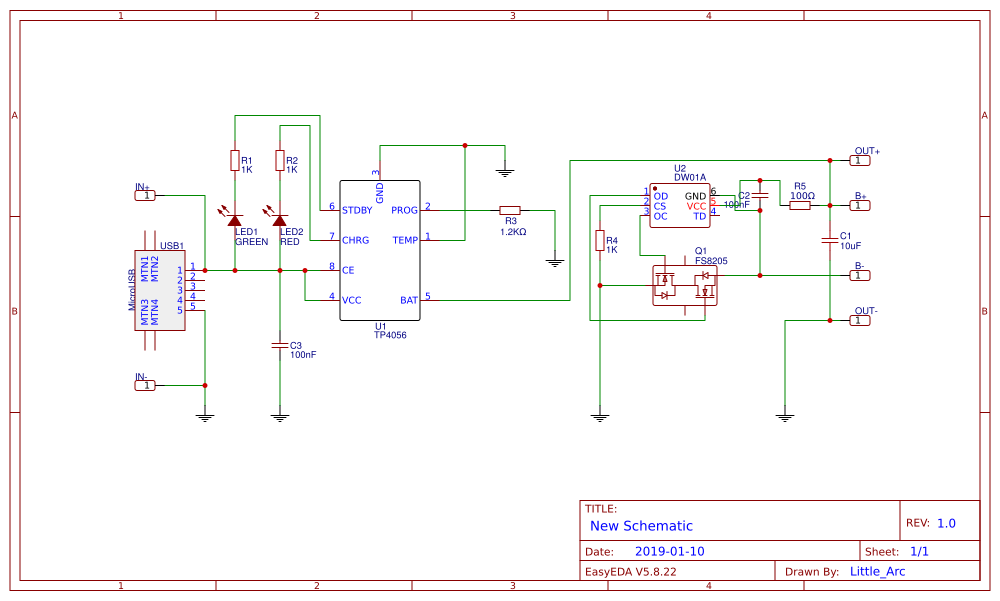
Web I've Only Found One Schematic With These Three Components Combined:
When switch s1 is pressed, transistor q2 is turned on by r3 and r1 to ground. Among them, the control ic controls the mos switch to turn on under all normal conditions to make the cell and the external circuit conduct. The below has been completely edited to provide a more full schematic.
Figure 1 Is A Typical Application Schematic For A Texas Instruments Bq29700.
Please refer to the schematic in figure 1 for the following discussion of the circuit’s operation. Those two mosfets are triggered by pins 1 and 3 of the dw01, which are described as: Web maximum charging current is set by a resistor between ground and one of the pins, default resistor being 1.2 kω resulting in 1 a current;
The Li Ion Battery Protection Circuit Module Schematic Allows For Safe And Reliable Use Of Li Ion Batteries.
Web ordinary 18650 lithium ion battery protection board usually includes control ic, mos switch, resistor, capacitor and auxiliary devices fuse, ptc, ntc, id, memory, etc. Lithium cells of the same age and part number can be paralleled and share one protection circuit.